
HIGH END
TURNTABLES
and
VACUUM TUBES
AMPLIFIERS
|
|
|
HIGH END |
Reprint from Sound practices
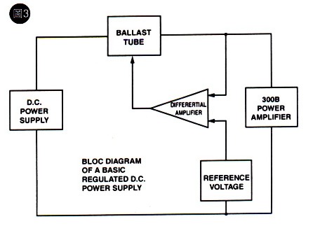
Design
|
|||||||||||||||||||||||||||||||||||||||||||||||||||||||||||||||||||||||||||||||||||||||||||||||||||||||||||||||||||||||||||||||
|
Resistance in cathode circuit of each triode separate, in ohms |
Number of triodes at parallel operation |
|||||||||||
|
1 |
2 |
4 |
6 |
10 |
over 10 |
|||||||
|
IA |
PA |
IA |
PA |
IA |
PA |
IA |
PA |
IA |
PA |
IA |
PA |
|
|
mA |
W |
mA |
W |
mA |
W |
mA |
W |
mA |
W |
mA |
W |
|
|
0 |
130 |
13.0 |
93 |
9.3 |
74 |
7.4 |
68 |
6.8 |
64 |
6.4 |
56 |
5.6 |
|
50 |
130 |
13.0 |
101 |
10.1 |
87 |
8.7 |
82 |
8.2 |
78 |
7.8 |
72 |
7.2 |
|
100 |
130 |
13.0 |
106 |
10.6 |
95 |
9.5 |
90 |
9.0. |
87 |
8.7 |
82 |
8.2 |
|
150 |
130 |
13.0 |
109 |
10.9 |
100 |
10.0 |
96 |
9.6 |
.94- |
9.4 |
89 |
8.9 |
|
200 |
130 |
13.0 |
112 |
11.2 |
104 |
10.4 |
101 |
10.1 |
98 |
9.8 |
94 |
9.4 |
|
250 |
130 |
13.0 |
114 |
11.4 |
107 |
10.7 |
104 |
10.4 |
101 |
10.1 |
99 |
9.9 |
IA - anode curent of one triode
PA - anode dissipation of one triode
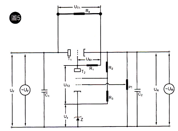
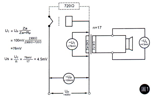
So for a minimum line voltage (-10%)
IR4 = YT1 / R4 = 100V / 1k
W 7 = 59 mA
and the dissipated power in the tubes will be
PT1 =100V x 191 mA = 19W1
for a nominal line voltage
UF= 550V,
UT1 + UF - UR = 600V- 400V = 150V
IR4-UT1/R4 =150V / lk
W 7 = 88mA
and the dissipation of the 6080 will be
PT1 = 150V x 162 mA = 21W3
For the case of maximum line voltage (+10%):
UF= 600V, UT1 = UT - UR
= 600V-100V = 200V
IR4=UT1/R4
= 200V / 1k
W
7 = 117mA
The current in the 6080 will be
PT1 = 200V x 133mA = 26W6
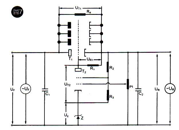
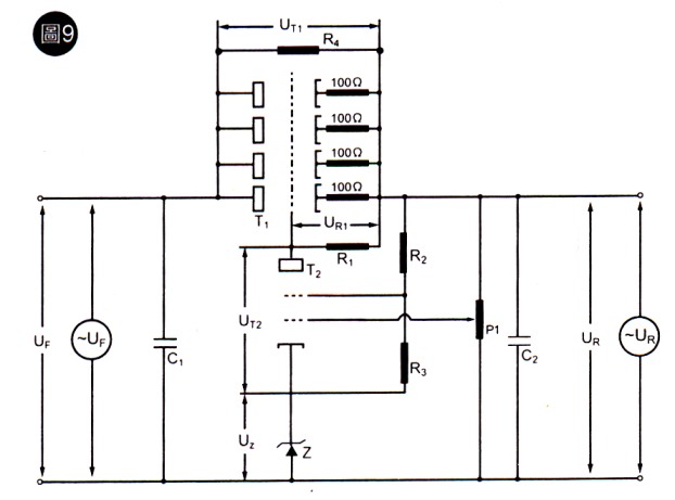
It appears that on the basis of power dissipation alone, one could be content with only one 6080. However, prudence commands to use two tubes for security's sake and for two other reasons.
1—Two tubes improves the regulation from the standpoint of residual hum and lower internal impedance of the power supply.
2—The variation between 6080 tubes is astonishing. It is an idle dream to find two tubes that are matched between sides and between tubes. Therefore, we must also wire in balance resistors in series with the cathode of each tube. The chart in Fig.6, published by SOVTEK gives useful information. For four triode sections in parallel in the absence of precautionary measures, the maximum power handling of each tube is not more than 7W4 and 29W6 for the quartet, thereby erasing our security limit entirely. Installing 100 ohm series resistors in series with each plate improves the situation such that the power handling becomes 9W5 x 4 = 38W
This arrangement is the second improvement we propose (see Fig.9).
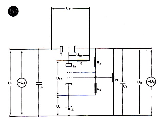
Design of the Differential Amplifier
The transconductance of the EF184 is 15000 micro-mhos in normal use. Here, the
transconductance is highly reduced owing to the very low current flowing through the pentode in
our special connection. Since the differential amplifier escapes calculation, it will have to be
estimated empirically, but we are mainly interested in the gain (and regulation factor)
we obtain. Maximum gain will be determined empirically by varying R1 using a 1M
W potentiometer. On the other hand. The values of R2, R3, and the
Zener reference voltage can be determined by calculation, considering the current through the
pentode as negligible and without any practical effect.
Zener Reference Voltage Choice It is a compromise. The higher the voltage, the more of the potentiometer will be in circuit. Since UR = UR1 + UT2 + U2 the Zener voltage is a compromise between the voltage drop across R1, the voltage between the plate and cathode of T2, and the voltage on the Zener diode. Given the realities of the components that we are using, we have to provide a reasonable operating voltage for the pentode. In view of this requirement, the error voltage applied to the grid of T2 through P1 must be limited to a certain value, even if the efficiency of the regulation is thereby decreased
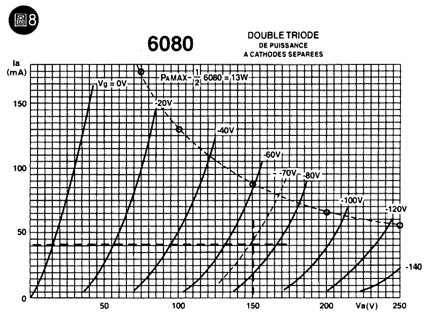
What is the voltage on the plate when the power supply is at nominal line voltage? We previously determined that in this condition, the current through the 4 x 6080 would be 162 mA (40.5 mA in each triode) and the voltage between cathode and plate would be 150V.
Referring to the curves of Figure 8, it is easy to determine that the grid voltage should be -70V. therefore, the plate voltage of the EF 184 is
UR - 70V = 400V - 70V = 330V
If we consider that it is wise to keep about 200V between plate and cathode on the EF184, we have
330V-200V = 130V
for the reference Zener voltage. Since 62V Zener diodes are readily available we can use two in series to obtain
Uz = 62V x2= 124V
The values of R2 and R3 will determine the current through the zeners. It is necessary to be very prudent in this, because zeners definitely don't like heat. The wattage rating given by the manufacturer must be severely derated.
We use B2X 85C diodes and they are specified for 1W3 or about 2.5 W for the two diodes. Taking a factor of 5 as a security coefficient, we would only dissipate 0.5W for the two diodes and 0.25W per diode. For a half-watt dissipation, the current should be
P/U2 = 0.5W/126V = 3mA9 ---- R2+R3 = UR-UZ/3mA9 = 70KW
We can choose to use 2 resistors of 39KW each, yielding a power dissipation of 0.22W per diode at 3.5 mA.
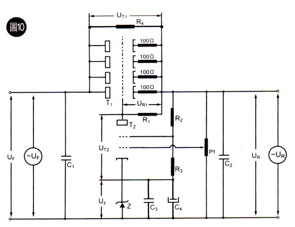
I believe that modern Zener diodes are better than glow discharge VR tubes in terms of noise and internal impedance. However, it is absolutely necessary to bypass them with a high value capacitor. We use a 100 microfarad electrolytic capacitor (C4) paralleled with a 0.47 polystyrene. This is the third important improvement on the basic circuit of Fig. 4, as pictured in Figure 10. The bypass capacitors eliminate residual hum on the regulated output and should be considered absolutely essential. It is not possible to adequately bypass a glow discharge VR tube because a VR tube and capacitor in parallel has a tendency to provide an excellent generator of sawtooth waves!
Choke Filter Elimination
The above discussion does not address rectifier and filter problems coming upstream of
the regulator circuit we describe. A good regulator allows us to forego a choke and use only
one capacitor after the rectifier.
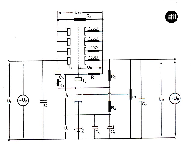
The rectified and filtered voltage Up is wired to Grid #2 of the EF184 pentode through C5 and adjustable resistor R5. This capacitor should present a negligible resistance at 100 Hz (120 Hz for the USA) We use a 0.47 for C5. There is no sensible progress in increasing the value. In any case, R5 allows a fine adjustment of the compensation. This is the fourth improvement toward making the best of electronic regulation, shown in Fig 11.
Controversy on Rl Dteposition
Some writers have indicated other solutions to power the load resistor of the pentode tube,
Rl.
1st Variant: The resistor is connected before the regulation on UF
In this case, the voltage UF is always more than UR, Therefore the
current is increased through the pentode and, consequently, its transconductance is increased.
And, the efficiency factor is increased also.
This is an advantage, but unfortunately, there is the problem of hum which does not exist in
the UR Connection.
2nd Variant: The resistor is connected to an increased external voltage source.
If the auxiliary voltage is very well-filtered, the result is indeed improved. However we
have to pay for this improvement with a substantial increase in complexity if the auxiliary
supply is not already in place. Therefore, we chose not to adopt that strategy.
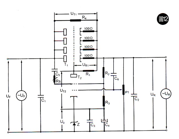
Lastly, there is another simple way to improve the regulation. We install a capacitor C6 between the upper terminal of potentiometer P1 and its moveable contact so that any variations in UR Are conducted directly to the grid of T2. This represents the fifth and last improvement we propose (Fig. 12).
Results
All those efforts to put this regulated supply into place truly pay rewards. The benefits
are clearly evident in the measurements, taken in actual conditions of use powering a stereo
300B single-ended amplifier and 2x 6BQ5 in the input stage. The actual current flow is 250mA
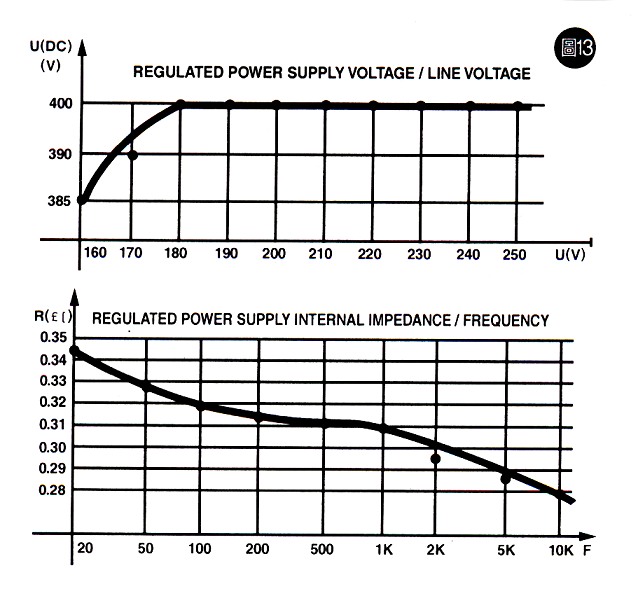
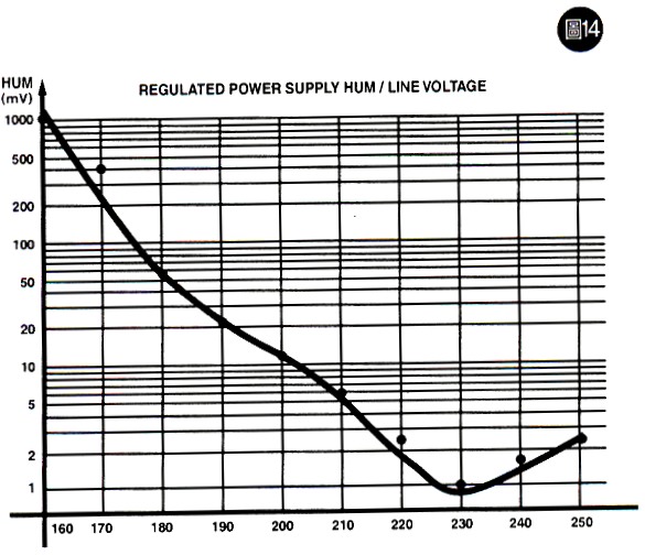
with the output voltage at 400 V. The curve shown in Figure 13a indicates the regulation area.
The voltage on the primary of the power transformer is varied with an auto-transformer.
The voltage is stable at 400V under line voltage variations between 180V and 250V
(and probably more, but 250V is the limit of our auto-transformer). This 20% security zone is
very comfortable, even though we may never use it in practice.
Experience shows that when the hum stays lower than 10mV, the signal to noise ratio of the amplifier is not seriously affected. This hum level becomes evident with a line voltage decrease of about 12%. Taking this as the limit of the regulator, the security zone of the regulator is still quite considerable.
The practical results demonstrate the reliability of the calculations and suggest that the method outlined above would be useful for the design of other power supplies.
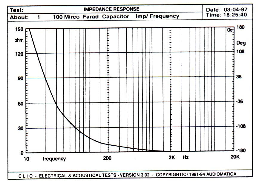
Finally, the measurement of internal impedance as a function of frequency given in Fig. 13b is most pertinent. The amplifier is driven to maximum power by a sine wave generator between 20 Hz and 10 kHz. The millivoltmeter is connected to UR through a 100 microfarad capacitor, large enough not to affect the frequency response of the test setup.
At 20 Hz, the internal impedance of the power supply is less than 0.35 ohms. To obtain the same result with a capacitor would require 22,000 microfarads. This demonstrates that a regulated power supply offers a large improvement and at a cost that is practically the same (considering that the filter choke is removed). The result is near perfection.
 |
 The regulated power supply can cure both of these problems,
by decreasing the hum below the thermal noise level and providing
an internal impedance lower than I ohm at all reproducible audio
frequencies.
The regulated power supply can cure both of these problems,
by decreasing the hum below the thermal noise level and providing
an internal impedance lower than I ohm at all reproducible audio
frequencies.
 Let us examine how we might keep these inevitable failings as negligible as possible.