
HIGH END
TURNTABLES
and
VACUUM TUBES
AMPLIFIERS
|
|
|
HIGH END |
|
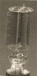
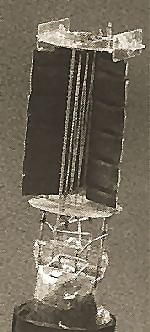
For a better resolution of the diagrams, put your screen on 1024 x 768 Pixels. The producer of tube amplifiers has a very difficult task to fulfill. It is an important affair because the satisfaction of the customer is in question. That satisfaction is most often based on a simple criterion explained as follows: "Some years ago, I bought an amplifier, it is good and works well" - or, unfortunately: "The amplifier I bought is not good because it always fails." We all know that failure in an amplifier is practically always provoked by the power tubes and for two main reasons: a ) The tubes are used beyond their official characteristics of voltage, current and power. The a) point can easily be improved, it is sufficient to take a safety margin in the value of B+ applied on the anode of the power tubes, without forgetting that for a main voltage of + 10% the B+ voltage will follow the same increase. Yes it is easy now, but only 10 years ago a customer was very shocked if we presented a push-pull amplifier with 6BQ5 with less power than 17 Watts or another one with 6CA7 unable to give 50 Watts well packed as in a parade like in the RCA handbooks. Yes the customers understand that now, too much available power has to be paid for swiftly, even very swiftly, by serious failures, and today the push-pull with 6BQ5 gives 8 to 10 Watts and their elder brother with 6CA7 stays around 25 Watts. There is only one problem, that kind of circuit is considered old-fashioned in light of triode single ended amplifiers with direct heating. The 3OOB triodes, hard to find some years ago, are now the subject of diverse offerings from various sources. The manufacturing qualities, the ability of the producers, and the often very high prices are each subjects for investigation. I have to answer them very carefully for myself at any moment to always keep the quality/price ratio of my product attractive. To get the answers, I put in place a special checking process dedicated to the 3OOB. Four different chapters will follow, they must take place at least on lots of 10 pieces to be significant. APPEARANCE TEST That begins by the measurement of the weight of the tube-a simple scale for letters will be enough. That measurement is very indicative of the global quality of manufacturing, because it indicates a possible tendency to quibble on the materialis quality used, even if a material such as glass or steel should be a very low cost compared with the price of a finished tube. After that come esthetic appreciations about the fitting inside the glass bulb. Examination of the micas is also important. Split or nicked micas are the result of a less careful assembly process. In that case, some mica parts bounce around inside the glass bulb. We must look carefully at the glass where the dumet wire leads pass through the glass stem. If the tube has received big shocks during transport, the glass can chip, leaving tiny bits of broken glass to jump around inside the glass bulb. The problem of inadequate packaging is quite impossible to solve because that work - really fundamental - is often left to an incompetent and changing staff impossible to suitably train. The previous observations can be made on the whole tubes. To pursue the examination, we must break the glass bulb, of course that will be made only after all the measurements described below are finished' When the glass bulb is broken, we have to open the plate with very little cutting pliers - in order to avoid deforming anything and observe the grid and the filament. The grid must not show any distortion. Sometimes we see that a grid spire has been hit unfortunately and that the two next grid spires are shorted together leaving a large free space for electron flow. Another common failure is the spraying of the electron emissive coating. It is applied too high on the filaments, leaving a surface of emissive cathode more or less above the grid, which is then unable to control the electron's flow. That defect combined with the first one gives a tube where the grid is not able to control completely and continues to let .flow a little current even for negative grid voltages as we will see during the electrical test. Failure of the visual tests as described above is a bad sign and the forecast of a rapid deterioration before the final cut.
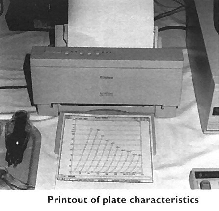
MEASUREMENT OF CONSTANTS: Amplification Factor, Plate Resistance, Transconductance Computers help the producers to automate complete measurements of the tubes. Before that it was unthinkable to make complete measurements because of the very substantial time investment they could take. A good technician could draw a network of power triode characteristics in about one hour (if he worked as quickly as possible ) with a conventional instrument such as our METRIX U61. Probably the same operator could have taken some liberties interpreting results-how can he reject a tube as he made the measurements of it in one hour? A capable technician would probably beg and implore us to avoid making him do stupid work. So, this was the reason why it was not possible to measure all the tubes systematically. Like I described above, times have changed.
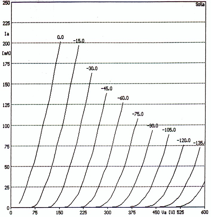
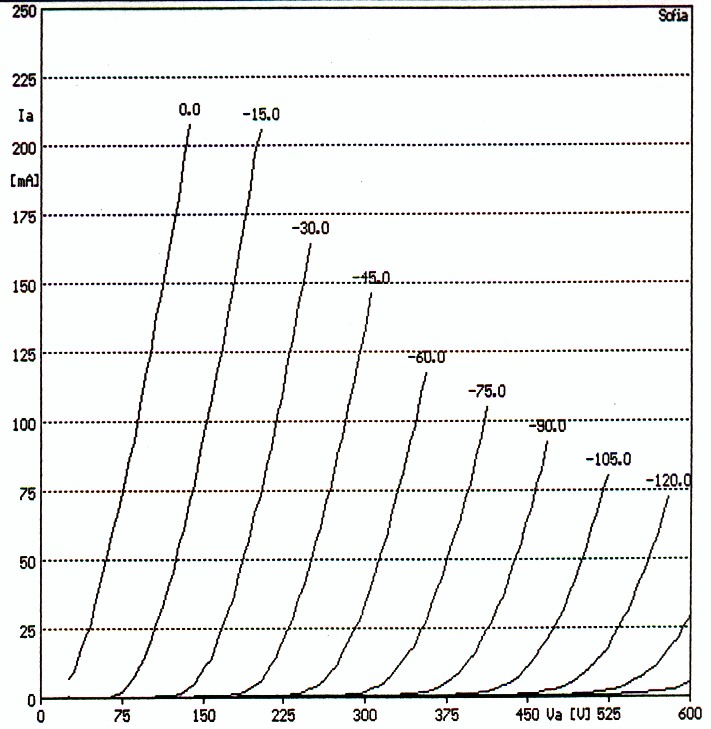
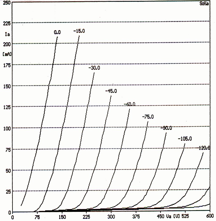
Those who imagine that 300Bs having the characteristics shown on the graphs are rarities make a mistake, I meet some of them during any measurement campaign. That failure is provoked by the imperfections described in the preceding paragraph about the step of the grid and the spraying of the filament. In fact that failure mode provokes a flatness of the signal for sine waves which wears the grid towards the very negative areas, near cut-off. That gives an important increase of "pair" harmonics (the ones which are pleasant for everybody), we have to ask a question on this matter: is that failure provoked deliberately by the manufacturer of the tubes to give a warmer sound to his product? [Nah, I think they just messed up. -ed.]
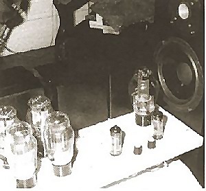
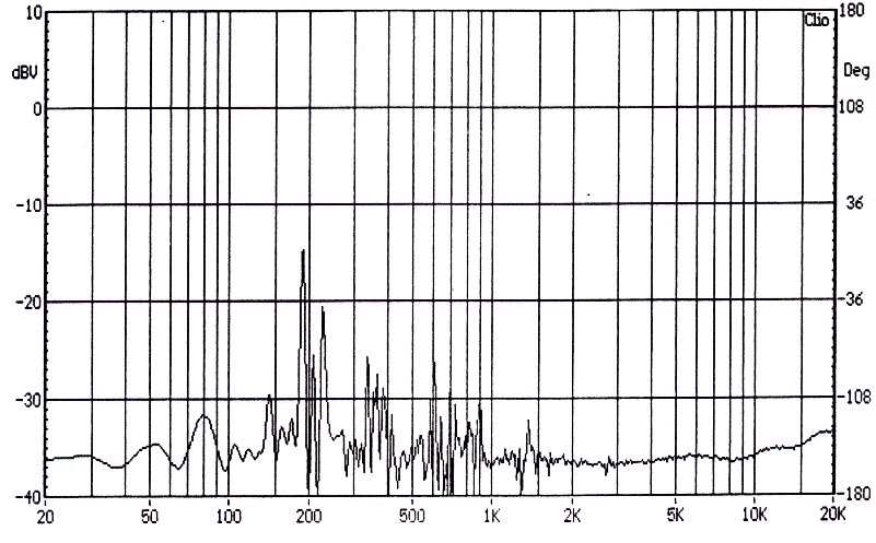
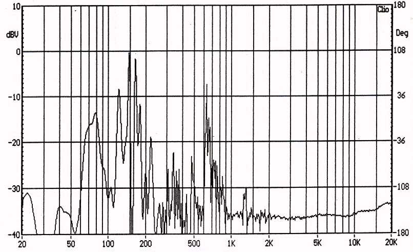
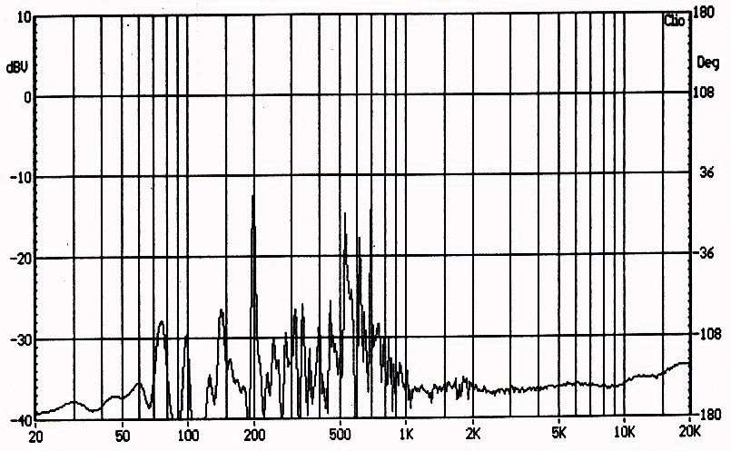
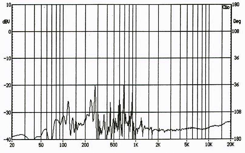
MICROPHONIA All the 300B tubes have a tendency to be microphonic. We used to tap on the glass bulb to check this parameter, but I think a measurement is better. The setup for the measurement I devised includes the following: a good size power amplifier (I X 70W Monobloc in class A); a loudspeaker able to receive the power (JM LAB Profil 3); a test amplifier (2300B modified ) to power the tube we have to test. The CLIO is programmed to come out and analyze 5 consecutive salvos of MLS sound. That signal is applied to the 70W amplifier which modulates the JM LAB loudspeaker itself placed as near as possible to the 300B tube under measurement. The amplifier carrying the 300B is prepared for the measurement, the grid of the 300B is wired to the ground to prevent signals coming from the preamplifier stage from disturbing the measurement. The output of the amplifier is connected to the input of the CLIO which makes a FFT analysis of the MLS salvos of sound and shows the average measurement on the PC screen. During the measurement, the operator has to wear hearing protection. That noisy test is very indicative of the rigidity of the tube's internal mechanical fitting. We can see important differences between productions with microphonia sensitivities varying up to 20dB for one model to another. Examination of the graphs also shows that there are 2 main resonances. One is due to the filament movements and is generally situated about 150-200 Hz. The other has about the same magnitude but a higher frequency (about 500-700 Hz) which corresponds to the grid vibration. It is clear-listening tests show it-that a less microphonic power tube is better when we listen to it, for a simple reason: if electrodes are mechanically unsteady and move and vibrate according to the violent sounds provoked by our measurement, they also move when they are at work for a musical reproduction, perhaps according to the variation of the internal electric Fields. However, this explanation is a hypothesis, it remains to be demonstrated scientifically.
That 300B - high quality construction - but atypically the graphs show a preponderance
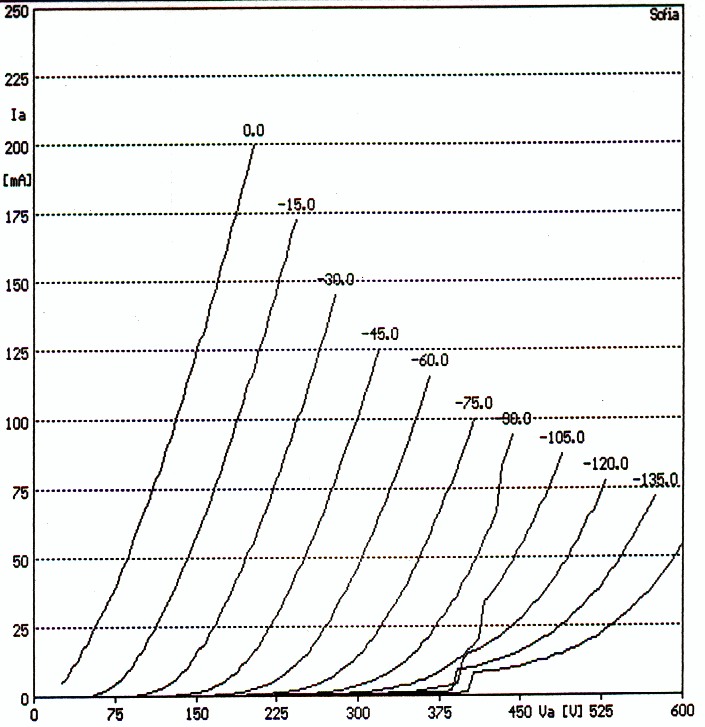
Very hororably good and typical result, it indicates precisely that we are facing a high quality production unit.
The best result obtained on those first measurements, Good blood cannot lie.
COMPARATIVE VACUUM TESTS A good vacuum is essential for electronic tubes. A poor vacuum reveals defective manufacturing. It can mainly indicate that there are leakages-certainly tiny ones- but they will shorten the lifetime of the tube. It also indicates that the manufacturing process is not completely perfect and has not been properly finished. A bad vacuum does not allow stable work conditions, especially since it promotes ionization of internal areas when high voltage is present. Perhaps it is useful to explain the process of pumping modern tubes to clearly understand the whole problem. The method I describe here is a digest of a very complex reality which can be different from one manufacturer to another and also according to the model of tube. After being completely assembled (but without its base) the exhaust pipe of the tube is connected to a double pump system fitted in series consisting of a primary pump producing a rough vacuum and a molecular pump producing a strong enough vacuum to allow heating voltage and high voltage without formation of electrical sparks between the electrodes. During the pumping, the tube is surrounded by a coil excited by a high frequency current to heat the electrodes by induction. Simultaneously, the electrodes become red hot due to the high frequency heating, the oxides sprayed on the filament are reduced to form the final cathode emitting electrons, and the getter (a kind of little cup containing magnesium) is evaporated by the heat. Thanks to this process, the last gas inside the electrodes is drained off and captured by the magnesium of the getter which contains them when settling on the internal part of the glass bulb by condensation to form a reflecting area like a mirror. After all those operations, the tube is cooled and installed on its base, and it will undergo the final formatting operations of the cathode and all the tests dedicated to show its good working or its rejection. Now, I present all my apologies to the specialists of tube production who read the previous prose which doesn't do justice to the incredible complexity and the astonishing know-how in action to lead the operations I described with so much simplicity. For example, two or three things I know or believe to know: The production of the 'mixture' coated on the filament to form the future cathode consists of about 300 different chemical components which must be perfectly pure. The vacuum is considered as good for a value of 10^-6 mm/Hg. To obtain that figure, it is necessary to eliminate a proportion of 1,000,000,000 gas molecules for I remaining. Yet the remaining molecules number an amazing 28,000,000,000 by cubic centimeter of "good vacuum." The comparative measurement I propose seeks to underline the presence of those undesirable gas molecules by bombing them with the electronic current of the tube in function as shown on the diagram. We see that the plate becomes positive by a voltage coming from an adjustable regulated power supply while the grid receives a negative voltage of - 50V. The voltage of the plate is adjusted for each measurement so that the plate current is always 100mA. A micro ampere meter is inserted in the grid circuit and indicates the concerned measurement by the following mechanism: The grid being negative pushes away all the electrons moving between cathode and anode, but it attracts and captures the positive ions produced by the shocks resulting of the impact between flow of electrons and undesirable gas molecules remaining in the glass bulb. 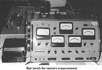 The ionic current indicated by the micro Ampere meter is compared with the whole electronic current and shows a number we call vacuum
factor. Theoretically it is possible to calculate the real vacuum (in mm of Hg) from this vacuum factor and to consider the dimension of the different
electrodes, but that precision does not concern us here, as we are comparing tubes of the same type with practically the same
characteristics. The ionic current indicated by the micro Ampere meter is compared with the whole electronic current and shows a number we call vacuum
factor. Theoretically it is possible to calculate the real vacuum (in mm of Hg) from this vacuum factor and to consider the dimension of the different
electrodes, but that precision does not concern us here, as we are comparing tubes of the same type with practically the same
characteristics.
During these measurements, I made interesting and amazing observations. Very used tubes generally have a better vacuum factor than the new ones. The ionic current of a new tube, abnormally high at first, is stabilized after some minutes of work at a correct value. I found only one tube with a bad vacuum, unsteady and higher than the average. No doubt that the vacuum is the most delicate parameter to obtain but it is also the most watched during production.
ABOVE : Measurement chart of the ionic current
CONCLUSION The reader will have noticed that all the measurements published in this article are only given for example, no trademark is mentioned. The reason is that some of the results were very bad. I could not do it without the agreement of the firms concerned, because I risk big reprisals. I would like to publish in a future issue of Sound Practices a truly comparative article. To do that, it would be necessary to receive samples from the producers or distributors with the authorization to publish the measurement results. I think that it will be difficult to put in place, but one is always allowed to hope !
|
 |


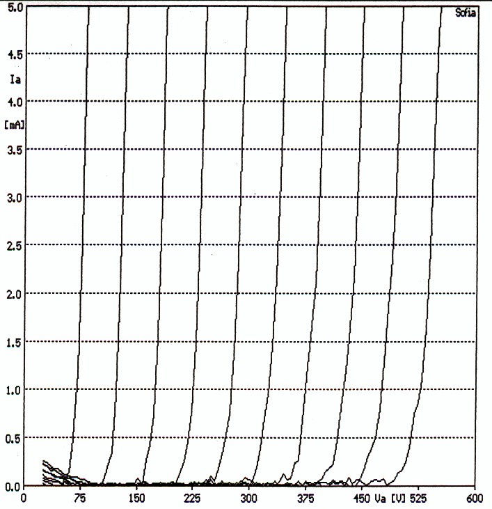
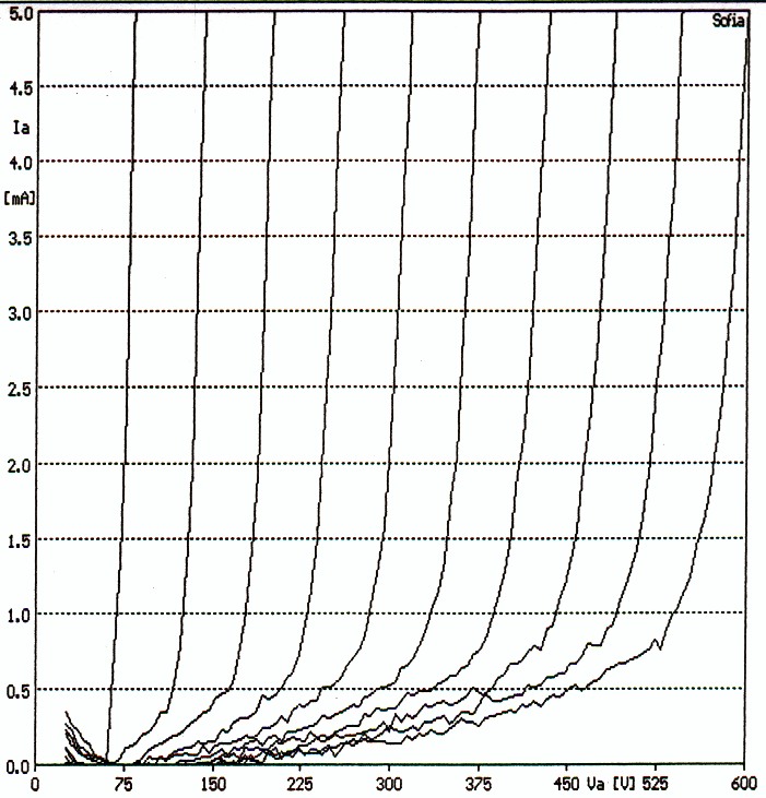
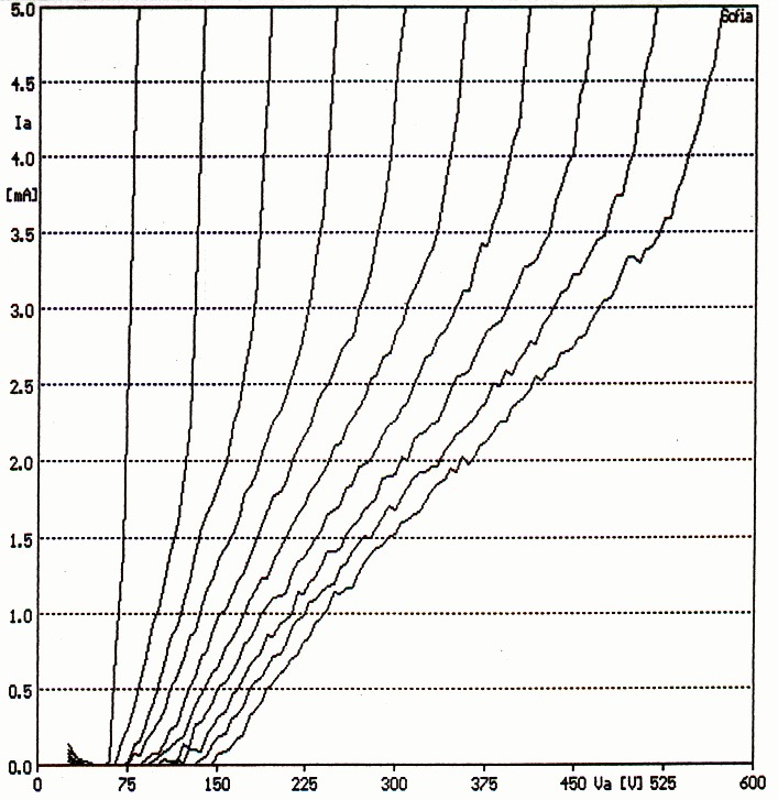
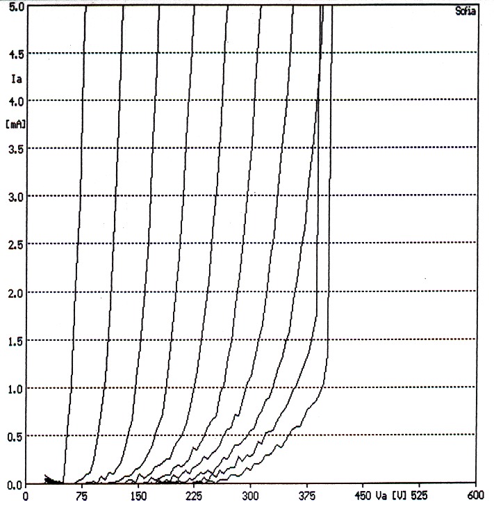
 Now, with an ordinary PC and a system such as Audiomatica's CLIO, one can measure and record all the characteristics of tubes in a way which is nearly a pleasure. Matching is made easy by superimposition of the characteristics and it is possible to appreciate the linearity given by the tube when it is in place on the amplifier. We clearly see on the drawings the colossal differences between a very good tube, an acceptable tube or a completely bent tube. And more, we can expand the base of the curve by the variation of abscissa scale and remove any doubt.